¶ Introduction
Flowol is one of the programming choices in Robot Mesh Studio (RMS). You can use Flowol flowcharts to program VEX IQ and EDR robots, the new VEX V5 controller, all VEX Mimics, and the Classic Mimics. In this guide, you will learn how to program in Flowol using Classic Mimics, and how to use the Classic Mimics in education. Robot Mesh Studio with Flowol replaces older versions of Flowol, although Robot Mesh continues to support Flowol 4.
Flowol allows students of all ages to develop logical reasoning and problem solving talents, develop programming skills and explore the world of automatic, autonomous systems and robots. Programming visually with a flowchart allows the student to focus on the logic of their solution rather than the syntax of a written program. Flowol supports many programming elements:
- Sequences of instructions
- Branching using decisions
- Loops (infinite, or based on a condition or count)
- Variables and simple variable manipulation
- Sub-procedures (parameters optional)
- Multiple parallel threads
Keys: Uses standard flow chart logic, generates code you can execute on your VEX or VEX IQ robot, or in one of our Classic Mimics.
Use for: Robot or Mimic programming using flowcharts
Check the Flowol Language Guide for a programming language overview and to see syntax descriptions. We expect that you have reviewed the Flowol Language Guide before starting these activities.
¶ Flowol Programming
This is a hands-on approach to learning Flowol using mimics. We present some of the mimic models and walk you through programming.
¶ Robot Mesh Classic Mimics
Flowol is bundled with a series of mimics. Some show road and traffic features, and in these cases there are often two mimics, one for the United Kingdom market (and other countries where traffic drives on the left) and another for the United States market (and other countries where traffic drives on the right). One example of this is the Zebra Crossing mimic for right-hand drive countries, and All Stop for left-hand drive.
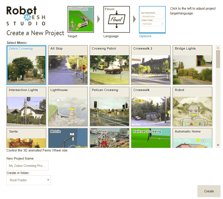
¶ Creating a New Classic Mimic Project
Open www.robotmesh.com/studio:
- Click on Create a Project
- Then, in the Create dialogue:
- Choose "Classic Mimic" as the Target
- Choose your desired programming language
- In the Options, choose which mimic you want to work with.
- Click Create
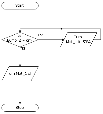
¶  Zebra Crossing
Open the Zebra Crossing mimic. Students in countries where cars drive on the right should skip this and go on to "All Stop."
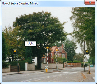
To see what the mimic can do, click on the light in the picture.
¶ Activity

- Create the instructions (a program) to control the light by building this flowchart.
- Click and drag each symbol from the left toolbar and place it on the workspace. Use the prompt box at the bottom of the screen to put the instructions in each symbol. Finally use the line tool to join up the symbols.
- Remember to add your own instructions to the blank symbols.
- Click on Run to see if your flowchart works.
¶  All Stop (US)
Open the All Stop mimic. It shows a fairly quiet intersection.
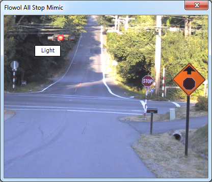
The pictures in Flowol are called Mimics and you can control them. To see what the mimic can do, click on the light in the picture.
¶ Activity 1

Create the instructions (a program) to control the light by building this flowchart.
Click and drag each symbol from the left toolbar and place it on the workspace. Use the prompt box at the bottom of the screen to put the instructions in each symbol. Finally use the line tool to join up the symbols.
Remember to add your own instructions to the blank symbols.
Click on Run to see if your flowchart works.
The example uses a delay of 2 seconds.
¶ Crossing Patrol
Create a project following the directions above, selecting the Crossing Patrol mimic.
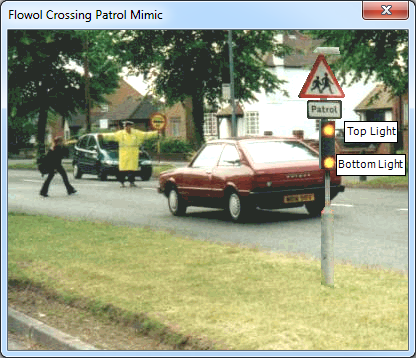
There are two lights on the signpost.
Create a flowchart to control these two lights. Click on Run to check your flowchart and then make any improvements.
Use the Label Tool to add a title to your flowchart.
¶ Crosswalk
Create a project following the directions above, selecting the Crosswalk mimic.
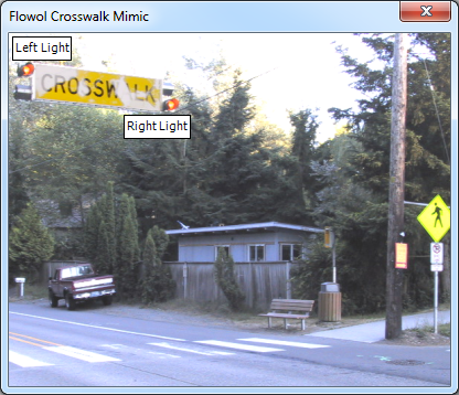
A crosswalk has two lights suspended above it.
Create a flowchart to control these two lights. Click on Run to check your flowchart and then make any improvements.
Use the Label Tool to add a title to your flowchart.
¶ Bridge Lights
Create a project following the directions above, selecting the Bridge Lights mimic.
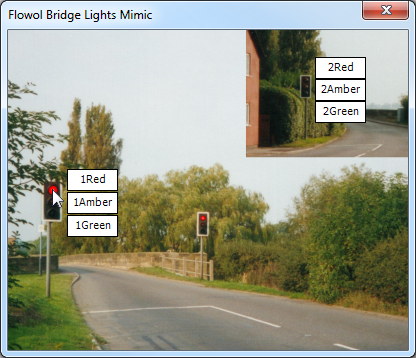
Explore how the mimic looks when the outputs are turned on by clicking on the outputs in the Status Panel.

¶ Activity 1
First, create a flowchart to control a single set of traffic lights.
¶ Activity 2
Now, modify your flowchart to control both sets of lights together. The flowchart might look like the one below.
Remember to fill in the empty symbols.
Click on Run to see if your flowchart works. And make any refinements or modifications if necessary.
¶ Tooltips
When an output symbol is controlling 3 or more outputs, the text may be truncated if it does not fit in the symbol. When this is the case, and you move the mouse pointer over the symbol, a tooltip will appear showing the full text.
¶ Intersection Lights
Create a project following the directions above, selecting the Intersection Lights mimic.
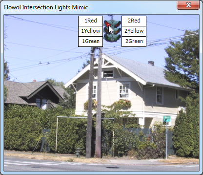
Traffic signals may hang from cables in the middle of the street like these, or be fixed to metal supports which reach over the road.
Explore how the mimic looks when the outputs are turned on by clicking on the outputs in the Status Panel.

¶ Activity 1
First, create a flowchart to control a single set of traffic lights.
¶ Activity 2
Now, modify your flowchart to control both sets of lights together. The flowchart might look like the one to the right.
Remember to fill in the empty symbols.
Click on Run to see if your flowchart works. And make any refinements or modifications if necessary.
¶ Tooltips
When an output symbol is controlling 3 or more outputs, the text may be truncated if it does not fit in the symbol. When this is the case, and you move the mouse pointer over the symbol, a tooltip will appear showing the full text.
¶ Lighthouse
Create a project following the directions above, selecting the Lighthouse mimic.
So far the systems have been controlled by a set of instructions which are remembered and repeated. In the next few mimics, the scenarios may need to respond to an external event such as a button being clicked or the daylight (brightness) changing.
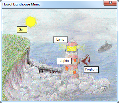
Open the Lighthouse mimic and explore by clicking on the three outputs: Lamp, Lights and Foghorn, and the input Sun.
The Sun input is representing a digital light sensor which is on when it is daylight. Click on the sun/moon to toggle it.
¶ Activity 1
Construct this control flowchart to turn on the flashing Lamp of the lighthouse at nighttime. Add some labels to your flowchart.

Note that you always need both a YES and an NO line from a decision symbol.

¶ Activity 2
Now create another flowchart on the same workspace to control the inside Lights. The inside lights should stay on when it is dark and go off automatically in the daytime.
Since both flowcharts have a Start, they will both run in parallel when you click run.
If you had problems, make sure both flowcharts are in the same project.
¶ Activity 3
Create a more interesting flashing sequence with a subroutine.

A subroutine must first be defined with the symbol. Once the subroutine has been defined, the Call Sub symbol will appear on the left toolbar. Use it in the main flowchart to call (invoke) the subroutine. In the example to the right, the Flash subroutine is run twice (x 2).
Now adjust the main flowchart to create your own interesting flashing sequence.
Subroutines are a great way to take a piece of tested, working code, in this case the lamp flash, and use it over and over again in the same program. This is a short program, but the more complex your programs get, the more valuable subroutines become. They make your flowcharts easier to read, and makes debugging them faster.
¶ Activity 4
Control the foghorn by constructing another flowchart.
¶ Pelican Crossing
Create a project following the directions above, selecting the Pelican Crossing mimic.
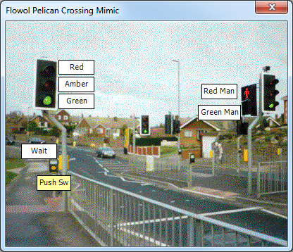
Click on the Push SW Input (the orange circle) on the mimic window. This is a push switch with goes off after ½ a second.
Also explore the Outputs to see what the mimic can do.
Split your solution into four separate statements.
¶ Activity 1
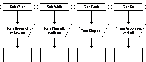
In this activity we will create a subroutine and use it for turning the various lights on and off, controlled by the logic and program flow in a main flowchart.
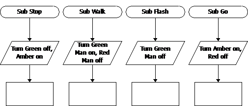
Construct and complete these four subroutines:
- To stop the vehicles.
- To indicate when it is safe to walk.
- To warn the pedestrians to clear the crossing.
- To allow the vehicles to move.
¶ Activity 2
Complete the main flowchart to call (invoke) the subroutines correctly.
¶ Crosswalk 2
Create a project following the directions above, selecting the Crosswalk 2 mimic.
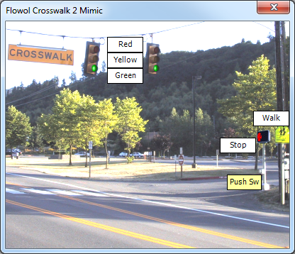
Click on the Push Sw Input (the small white circle) on the mimic window. This is a push switch with goes off after ½ a second.
Also explore the Outputs to see what the mimic can do.

Split your solution into four separate statements.
¶ Activity 1
Construct and complete these four subroutines:
- To stop the vehicles.
- To indicate when it is safe to walk.
- To warn the pedest- rians to clear the crossing.
- To allow the vehicles to move.
¶ Activity 2
Complete the main flowchart to call (invoke) the subroutines correctly.
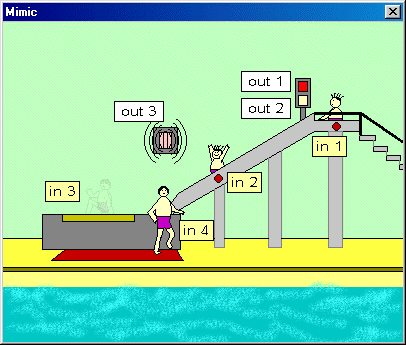
¶ The Robot
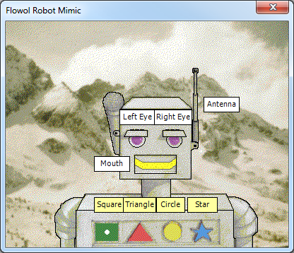
Create a project following the directions above, selecting the Robot mimic.
It has 4 inputs along its chest, and 4 outputs. Explore the mimic by clicking on status area on the right.
¶ Activity 1
Amuse your friends by constructing three or four separate flowcharts to control different movements of the robot.
¶ Activity 2
Construct a program to animate the robot's mouth making it appear that the robot is speaking.
¶ Activity 3 (Larger project)
Imagine that the robot is a toy for a young child who is just learning their colors and shapes.
Create a program for the robot toy which uses the colored chest buttons to make the mouth, eyes and antenna operate based on the shapes clicked. You could also make the shapes more active by having something with the mouth, eyes and antenna over and over. You could also make it so that more than one shape has to be clicked, for example, the antenna only goes up when both the square and circle are selected.
Remember to break the program into subroutines.
¶ Santa
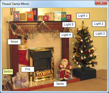
Season’s Greetings! Create a project following the directions above, selecting the Santa Mimic.
Use the Status Panel to see what the mimic can do.
¶ Activity 1
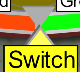
Using the Switch, construct a flowchart to turn the electric Fire on and off.
¶ Activity 2
Construct another routine to make Rudolph’s Nose flash when the Switch is on.
¶ Activity 3
The Christmas tree lights could be controlled in several ways. You could make them all come on together when the Switch is on. You could also make them all flash together, or they could twinkle if you have different groups coming on and off at different times. Create your own program to control the lights.
¶ Activity 4
Santa’s movement can be controlled with the Santa digital output. Write a subroutine to move Santa once. Then create a main program to call (invoke) the subroutine and make him dance.
¶ Activity 5 (Advanced)
Use the Random function to have the Christmas tree lights flash in a subtle, but random fashion.
¶ The Crib Mobile
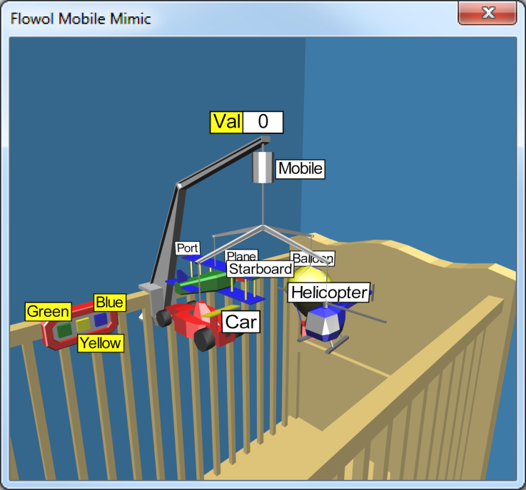
Create a project following the directions above, selecting the Mobile mimic.
A clockwork crib mobile can comfort and entertain a baby, but how could an automatic crib mobile be an advantage? Open the Mobile mimic, and show its labels. Explore what it can do by clicking on the outputs and motors in the Status Panel.
Click with the right mouse button on the motors to reverse them.
¶ Activity 1
Controlling the motor to rotate the whole mobile is the most impressive effect. Build this program to use the Green digital input to start and stop the Mobile motor.
¶ Activity 2
Motors can of course go forwards and reverse. Construct another two flowcharts to give some forward and reverse movement to the Helicopter rotors and the Plane propeller when the Yellow and Blue inputs are used.
Run the whole program. This should give some interesting combination movements when the three switches are changed.
¶ Activity 3
Another important control feature for a motor is to change its speed (or power). Modify your first flowchart to reduce the main rotation speed of the mobile for a while and then speed it up again. (Remember, if you reduce the motor speed percentage, then it must be returned back to 100% for full power).

So far we have used digital inputs which can only be either on or off. Another type of input can be from an analog sensor which detects a range of input values (e.g. analog values could be from different levels of light brightness, different temperatures or different volumes of sound).
The Mobile mimic has an analog sensor at the top of the mobile support arm which changes value when you click on the number with the left and right mouse buttons.
¶ Activity 4
Rename the analog value from Val to Light and treat it as a light level sensor. Construct an automatic light flowchart to turn on the light in the hot air Balloon if the light level goes below a value of 18 units (i.e. Light < 18).

¶ Activity 5
The baby should still be occupied before it gets quite this dark, so produce another one or two flowcharts to make the rear light on the Car and the Port and Starboard plane wing tip lights flash if the light level value goes below 60 units.
¶ Activity 6
The cot mobile would be most interactive if it could respond to the baby’s sound. So rename the analog sensor to Sound. Larger values represent a louder sound.
Rebuild the flowchart to respond to the sound that the baby is making. If the baby makes a quiet noise, some of the lights could turn on or flash for a while. If the noise gets louder, the rotors and propeller could start to move slowly, and if the baby gets very noisy, the whole mobile could become very active.
As the baby settles down, and makes less noise, the mobile should also slow its activity to sooth the baby back to sleep.
Finally, use the description pane in RMS to write some brief instructions for the parents.
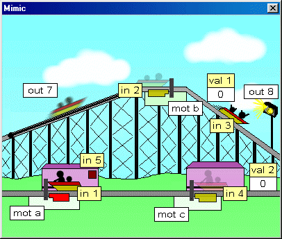
¶ Big Wheel/Ferris Wheel
Create a project following the directions above, selecting the Big Wheel/Ferris Wheel mimic.
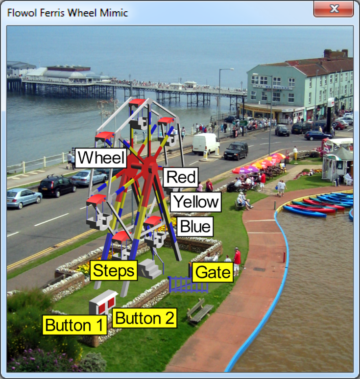
If you were the operator of a fair ride, how would you produce an exciting but safe experience?
Explore what the mimic can do by clicking on the inputs, outputs and motors on the Status Panel.
Button 1 and Button 2 are normal inputs but, when the wheel is rotating, you may notice that the Steps input flashes on each time a seat passes over the steps. Also, if you click on the Gate with the left mouse button you will find that the Gate input comes on when the gate is shut.
The Steps and Gate inputs are called virtual inputs. They cannot be changed by directly clicking on the mimic, but are changed by features within the mimic itself.
¶ Activity 1
To attract the crowd, use the Button 1 input to control the lighting effects on the wheel’s frame.
This might be a simple on/off routine but flashing sequences are more exciting. Use subroutines.
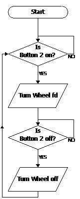
¶ Activity 2
Use the Button 2 input to control the simple Go/Stop movement of the wheel. You could perhaps make the wheel speedup and slowdown in stages by changing the motor power.
¶ Activity 3
Modify activity 2 to include the safety feature of the gate so that the gate must be closed before the wheel will start (i.e. both Button 2 and Gate are on). The wheel should stop if either Button 2 is turned off, or the Gate is opened (i.e. if either Button 2 or Gate are off).

¶ Activity 4: Counting how many times the ride is used
Add this symbol to the flowchart created above in Activity 2. This uses variable x to count how many times the ride is used.
¶ Activity 5: Stopping the Wheel Automatically
Construct this counting program to increase the variable y each time a seat passes the steps, i.e. each time the virtual input goes off and on.
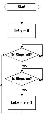
Since there are 7 seats, each rotation of the wheel should increase the variable y by 7.
Now modify your program by introducing a decision symbol, to stop the wheel automatically after it has rotated 3 times.
¶ Activity 6
Now that you have learned how to use the Steps input, create a subroutine which rotates the wheel and stops briefly at each of the seven seats for passengers to get on or off.
Call (invoke) this subroutine twice; once at the beginning to load the wheel with passengers, and then at the end to unload.
¶ Level Crossing
Create a project following the directions above, selecting the Level Crossing mimic.
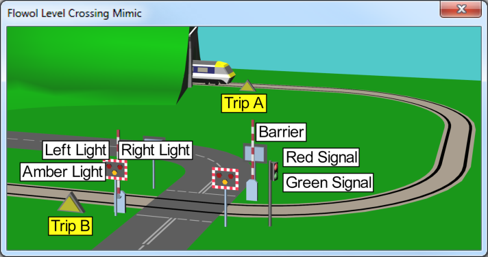
There are two inputs: Trip A and Trip B which cannot be clicked on. Instead they are triggered when the train goes past.

The train runs automatically whenever the flowchart is loaded into Robot Mesh Studio.

¶ Activity 1
Construct and complete the flowchart to the left to flash the Left Light and Right Light outputs when the train approaches, and turn them off when the train has passed by.
¶ Activity 2
Add symbols to control the Amber Light.
There is no Amber Light on the US version of this mimic, so this is skipped.
¶ Activity 3
The solution above is not quite correct since the lights stop flashing as soon as the front of the train reaches Trip B.
Modify the main flowchart to match the one on the right to correct this.
¶ Activity 4
The Barrier motor moves the gate. Turn it forward for a certain time period to close the gate and reverse to open the gate.
Create two subroutines, Gate Close to close the gate, and Gate Open to open it. Call (invoke) these subroutines from the main flowchart to close and then reopen the gate.

Replace the Delay in the Gate Close subroutine to call the Flash subroutine an appropriate number of times to keep the lights flashing while the barriers are closing.
¶ Activity 5
The train can be stopped in an emergency with the signal. To stop the train, turn Red Signal on.
Add output symbols in appropriate places to your flowchart so that the Red Signal is shown whenever the barrier is not down.
To verify that the signal works correctly, reduce the speed of the barrier so that it doesn’t have time to completely close by the time the train arrives at the signal.
¶ Activity 6 (Advanced)
Adjust the mimic options (click the check box at the top of the Status Panel) to use feedback switches on the barriers.
Re-run your existing flowchart to see how the barriers vibrate when they reach the feedback switches. Modify your flowchart to use the feedback switches to stop the barrier movement.
Now that the feedback switches are used to control the barriers, it’s hard to keep the lights flashing because you don’t know exactly how long it will take to lower the barrier. Therefore, create a separate, parallel flowchart which flashes the lights whenever variable x = 1. Then set variable x to be 1 in the main flowchart to start flashing the lights, and set it back to 0 to stop the lights flashing..
¶ Automatic Home
Create a project following the directions above, selecting the Automatic Home mimic.
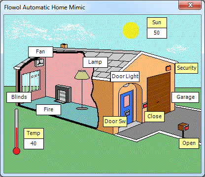
What automatic control features do you have in your home? What control features do you want?
¶ Activity 1
Construct a program to open the garage door when the Open button is pressed, and close it when the Close button is pressed.
¶ Activity 2
Assume that the Security digital input is a movement/infrared heat sensor which can detect a person on your driveway. Construct a program to turn on the Door Light when a person is detected.
Daylight Brightness and Temperature: By clicking on the numbers near the Sun and Temp thermometer, you can make the sensor readings increase or decrease in steps of 5. The sensors are calibrated by default as a percentage.

¶ Activity 3
Construct a flowchart, like the one shown, to turn on the inside Lamp only when the daylight Sun value goes below 50%.
¶ Activity 4
Construct another flowchart to make the electric Fire come on when the temperature goes lower than 30 units.
¶ Activity 5
Now control the electric cooling fan above the window. Think about the temperature threshold that you choose.
¶ Activity 6
What else can we do? The window Blinds can be controlled electrically. Make them automatic.
¶ Activity 7
Look at Activity 2 again, the one with the person detector. How can you improve this system? What would work if the sun is out?
¶ Greenhouse
Create a project following the directions above, selecting the Greenhouse mimic.
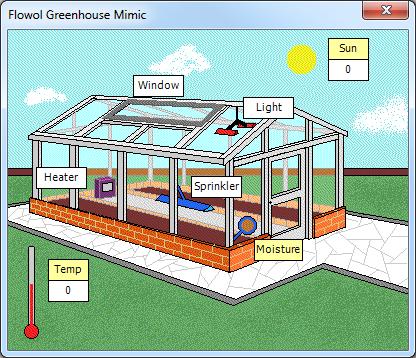
Why do we have greenhouses? Do some research and determine the best conditions for growing plants.
Open the Greenhouse mimic and explore its functions.
Moisture is a digital input that is off when the soil is dry and on when it is moist. The ambient temperature and light can also be measured with the analog Temp and Sun sensors.
You can control the Lights, Heater, Window and Sprinkler.
¶ Assignment
This is an open assignment. Apply your knowledge and skills to make this greenhouse look after the plants for you.
Make sure to label the different flowcharts to show clearly what you are trying to achieve.
¶ School Bus
Create a project following the directions above, selecting the School Bus mimic.
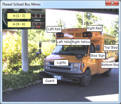
The driver has six buttons available to control the various lights, Stop Sign and Guard paddle. These buttons should be used in sequence to operate the safety features in the right order.
¶ Activity 1
Use the first button and build a program to operate the general front Lights.
¶ Activity 2
Create another program to control the flashing yellow lights to indicate to passing motorist that the bus is about to stop.
¶ Activity 3
The Guard paddle should then be deployed to ensure the children cannot pass near to the front of the bus.
¶ Activity 4
The red alternating traffic warning lights should then be activated.
¶ Activity 5
The Stop Sign should then be deployed.
¶ Activity 6
Finally the alternating lights on the stop sign should be illuminated.
¶ Train Set 1
Create a project following the directions above, selecting the Train Set 1 mimic.
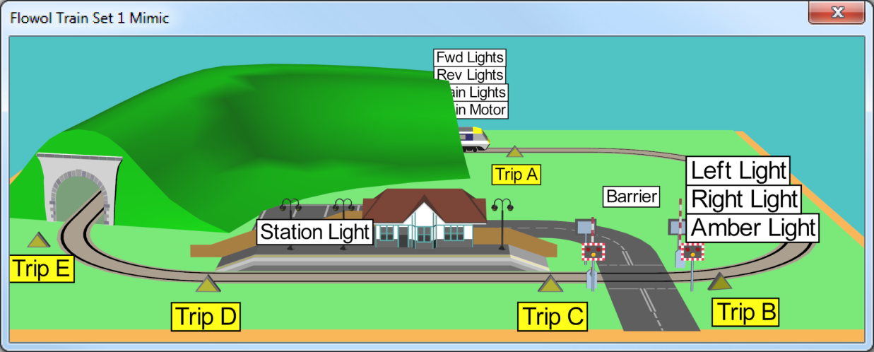
Add the labels and use the Status Panel to explore what the mimic can do.
Now imagine that you are the engine driver, the guard, the signal operator and station manager and manually control the train, its lights, the station lights, the crossing lights and of course the barrier gates.
You would probably be more successful, and safer, if you are just the engine driver and the other functions are controlled by a system created by you using Flowol.
¶ Activity 1
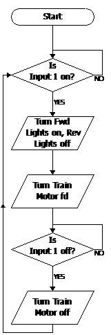
Since you are the engine driver, build this flowchart allowing you to use Input 1 on the input Status Panel to control the clockwise movement of the train.
¶ Activity 2
Now build a similar program to control the reverse movement of the train by using Input 2.
¶ Trip Switches
For the next activities we will assume that the train will be moving clockwise around the track.
You may have noticed that the moving train turns several input switches on automatically when it passes over them (the yellow triangles light up).
¶ Activity 3
To be energy efficient, build a program to turn the passenger carriage lights (Train Lights) on automatically only while the train is passing through the tunnel.
Note that the carriage lights should go on when the front of the train enters the tunnel and go off again when the back of the train leaves the tunnel.
¶ Activity 4
Now build a similar program to turn the Station Lights on only while the train is passing or is stopped at the platform.
¶ Activity 5
Apply what you learned from the Level Crossing/Railroad Crossing mimic to control the barrier and lights for vehicular traffic.
¶ Train Set 2
Create a project following the directions above, selecting the Train Set 2 mimic.
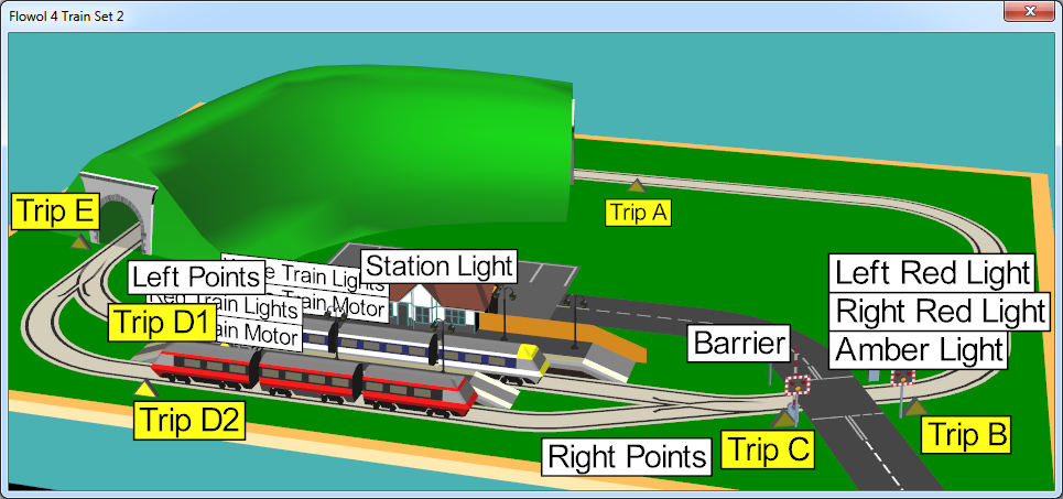
There are now two trains, and two sets of points (switches).
Each train has its own motor and lights. Click on the motors in the Status Panel to drive each train (right-click the mouse to turn the motor in reverse).
Each set of points (switches) are controlled by the Left Points and Right Points motors. Turn the motor forward to switch to the outside track and reverse to switch to the inside track.
¶ Activity 1
Create two sub-routines, one for switching to the outside track, and another to switch to the inside track.
¶ Activity 2
Create a master program which drives each train around the track one at a time.
¶ Activity 3
Incorporate all of the features from the mimic Train Set 1.
¶ The Horse Ride
Create a project following the directions above, selecting the Horse Ride mimic and click on the Front and Rear motors on the Status Panel to see what it can do.
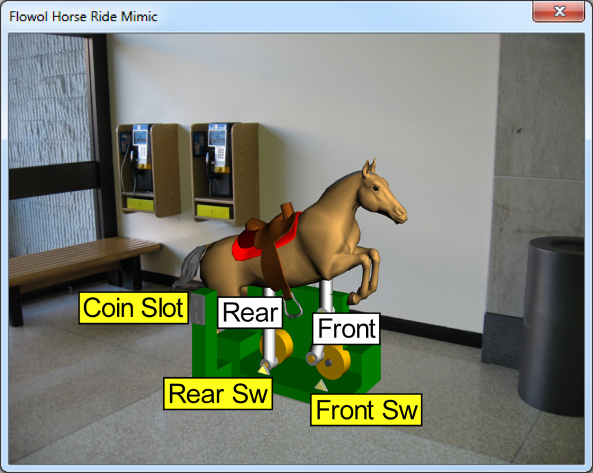
Coin operated rides are very popular in shopping malls, but rarely do we have the chance to see inside. While servicing this Horse Ride, the maintenance worker has removed the side cover so we can see the mechanism.
There are two virtual inputs on the ride: Rear Sw and Front Sw. They are switched on by the motors when the crank is at the lowest position.
¶ Activity 1
Build and complete this flowchart to drive both motors forward for 35 seconds when a coin is placed in the slot (Click on the gray Coin Slot).

¶ Activity 2
To make it easy for a person to dismount the horse, it should stop in its lowest position. Use one of the virtual inputs (e.g. Front Sw) and modify your flowchart so the ride stops at its lowest position.
¶ Activity 3
It might be a more interesting ride if the rear motor rotates slightly slower than the front. Adjust the top output symbol in your flowchart to run the Rear motor at 90% power.
¶ Activity 4
Create a second, separate flowchart (thread) to control the rear motor, so that the ride stops with both motors at their lowest positions.
¶ The Teacup Ride
Create a project following the directions above, selecting the Teacups mimic and click on the Status Panel to see how the ride operates. Having a ride in a teacup should be fun and safe.
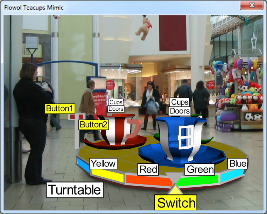
When the ride rotates (Turntable motor), the virtual input named Switch is turned on when the two triangles match up.
¶ Activity 1
Create and complete this flowchart to control the rotation of the ride with the left Button1. Run the program and click on the left red button on the mimic to toggle it on and off.
¶ Activity 2
To make the ride more exciting, spin the teacups (Cups motor) as well as rotating the turntable.
You could use delays with forward and reverse directions to make the ride even more interesting.
¶ Activity 3

The lights around the turntable rim (digital outputs Yellow, Red, Green and Blue) can add to the fun. Build a separate, independent flowchart to control these lights. You do not need to use the input since these lights should be attracting people’s attention the whole time. It might be interesting to use subroutines of different light sequences called (invoked) by the main flowchart to give variety to the light sequence.
¶ Activity 4
For this activity, you need to use the right button (Button2) to open and close the mechanical Doors on the cups. Create this subroutine to open the doors, and a similar one to close the doors. Now produce another separate flowchart (thread) to use these subroutines.
¶ Activity 5
For safety reasons perhaps the doors should only be allowed to open if the ride is stationary (e.g. if Button1 is off). Also the doors should close automatically if the ride is started with them open.
Make changes to your flowchart to add these safety features.
¶ Activity 6
It is useful to get off the roundabout at the same place where you got on. On the front of the turntable is a virtual input (named Switch) which is turned on by the triangle on the turntable.

Modify your flowchart so the ride stops at the right place when it is turned off.
¶ Extension Ideas
¶ The Pirate Ship
Create a project following the directions above, selecting the Pirate Ship mimic and use the Status Panel to explore what the mimic can do.

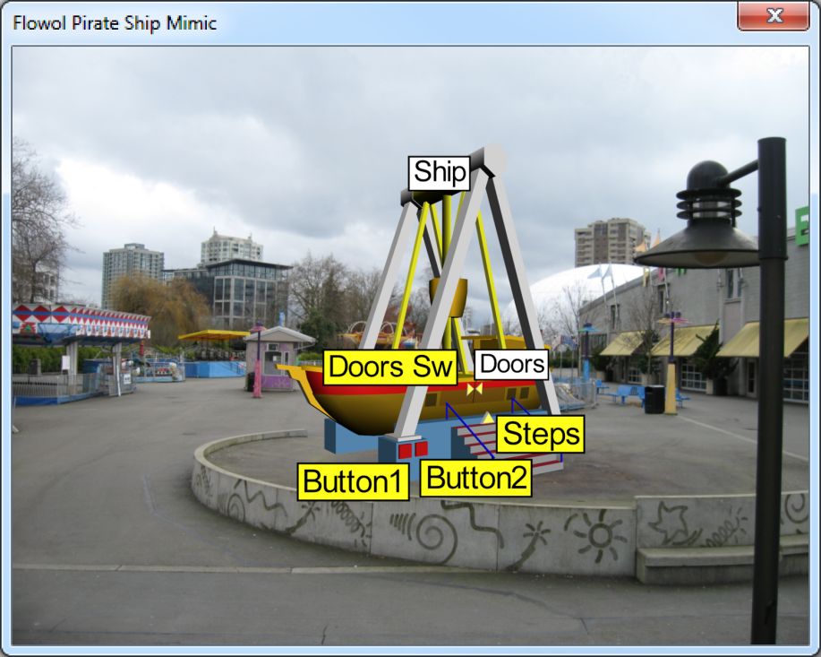
This Pirate Ship can be made to do exciting movements, but the theme park owner and safety inspectors would not allow them. Since you are the software engineer you need to create a control program which produces a thrilling, but realistic and safe ride.
The Doors Sw and Steps inputs (the yellow triangles) are virtual inputs and are triggered by the ride.
¶ Activity 1
To get the ship swinging we need to keep changing the motor direction about 0.7 seconds after the ship has passed its mid position.
Build and complete the Swing subroutine to reverse the Ship motor 0.7 seconds after the ship starts moving.

After it has swung back through the mid position (Steps input on), make the motor go forward again 0.7 seconds later. Adjust the 0.7 seconds value if needed.
Now use the Button1 digital input and build the main flowchart to call (invoke) the Swing subroutine.
¶ Activity 2
The next task is to operate the passenger doors in the side of the ship. Create two subroutines to open and close these doors (Doors motor) and build a second main flowchart which uses Button2 to call (invoke) the doors subroutines.
¶ Activity 3
Overcome this safety issue by controlling all the subroutines with just one main flowchart.
¶ Extension Ideas
- Gradually increase and decrease the speed of the swing. (Hint: build two more subroutines changing the speed (power %) of the motor in stages).
- Improve the safety by ensuring the doors are closed (Door Sw input) before the ship can start to move.
- (Advanced: Use variables to smoothly increase/decrease the speed and extent of the swing of the pirate ship for a very realistic ride).
¶ Grabber Game/Claw Game (Two button version)
Create a project following the directions above, selecting the Grabber Game/Claw Game mimic.
SPECIAL NOTE: this mimic has two modes: 2-button and 4-button. In the project creation dialogue there is an additional box that allows you to choose between 2 and 4 buttons. To do both parts of this mimic, you will want to create two projects, one 2-button and one 4-button. It is the same mimic with two options when you create the project.
Use the Status Panel to see how the mimic behaves.
To begin with, use this mimic in its default, two button, configuration.

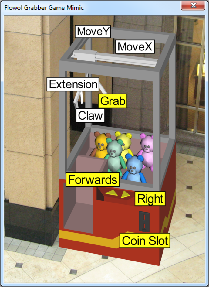
The mimic has 4 motors. MoveY, MoveX and Extension move the grabber. The Claw motor opens and closes the fingers of the claw.
Inputs Forwards and Right are push buttons which stay on while the mouse button is held down (or use the arrow keys on the keyboard).
The Grab input is a virtual sensor which is on if a teddy bear has been caught.
¶ Activity 1
Build this subroutine to move the hoist forwards. Build another subroutine to move the hoist to the right.
A third subroutine (named Home) is now needed to return the hoist to its near, left position. (hint: reverse both motors for about 2 seconds).
Now construct a main flowchart which calls (invokes) these subroutines when a coin is placed in the slot (Coin Slot input).
¶ Activity 2
Construct 4 more subroutines to open, lower, close and raise the grabber/claw and include them into your main flowchart to complete the game.
¶ Grabber Game/Claw Game (Four button version)
Please see notes above for the 2-button version to see how to select the 4-button version of the mimic.
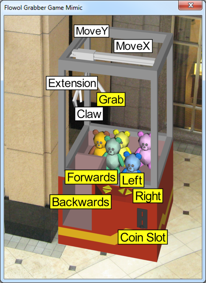
Now click on the Mimic Options button in the Status panel to set the mimic to use Four Buttons.

Now there are 4 directional inputs: Forwards, Backwards, Left and Right.
¶ Activity 3
Extend the solution in activity 2 by adding backwards and left control to the hoist. Modify the main routine to move the hoist with the buttons Forwards, Backwards, Right and Left in this order.
This gives the player an opportunity to correct if they overshoot the location of their target teddy bear.
¶ Activity 4
The 4-button game normally runs a little differently. It allows the player to push any of the 4 buttons in any order, for a pre-determined time limit before the grabber drops and attempts to grab a bear.
We therefore need a timer to interrupt the player operating the buttons. First add the Variables to you flowchart by pressing the button at the top-right of the Flowol window.
Then, add this flowchart to your workspace. Once the Coin Slot is activated, it increases the variable x at 1 second intervals to a maximum of 6.
Modify your main routine to allow the buttons to be pressed in any order until the time limit is reached, after which the grabber lowers to see if a bear has been won.
¶ The Car Park/Parking Lot
Create a project following the directions above, selecting the Car Park/Parking Lot mimic. Click on the inputs and outputs to explore how the mimic behaves. When you pick this mimic, just underneath the mimic pictures you will see a box labeled "Mimic Options." Click here to choose UK or US settings to determine whether the mimic shows the traffic driving on the left or the right side of the road.
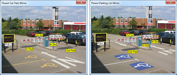
Parking restrictions can sometimes be inconvenient, but what advantages come from using a car park/parking lot?
¶ Activity 1
Construct a flowchart, similar to the one to the right, to open the In Barrier when In Sw is pressed and to close the barrier when In Pad is pressed. (Remember the subroutines must be created first).

¶ Activity 2
Construct another program to control the Out Barrier in a similar way.
¶ Activity 3
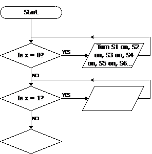
Add Variables to the flowchart by clicking on the button at the top-right. Then use variable x as a count of the available parking spaces. When a car enters, count down x. When a car leaves, count up x.

Insert the following symbols at the appropriate places. Run your flowchart and check that the value of x changes as you expect.
¶ Activity 4

Now drag and drop a new Start symbol onto the same page to create another parallel flowchart (thread). This flowchart should control the FULL sign when no parking spaces remain.
¶ Activity 5
When the car park/parking lot is full, the In Barrier should not allow more cars to enter. Add an extra decision symbol so that the In Barrier will only open if the In Sw is pressed and x > 0.
¶ Activity 6
Similarly, the out barrier should not open if there are no cars to come out.
¶ Activity 7 (US Project Only)
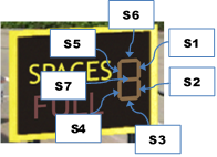
Knowing exactly how many spaces are available in a particular area could be useful. Give this information to the public using the 7-segment display next to the FULL sign (outputs S1 – S7).
Do this by dropping another Start symbol on the page and using this flowchart to continually set the on/off state of the 7-segment outputs depending on the value of the variable x. When the output symbol gets too full of text, hover over it to see a tooltip.
Remember to add labels to the workspace to indicate what each section is trying to achieve. (Only the US version of the mimic has the multi-segment display.)
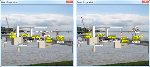
¶ The Lifting Bridge
Create a project following the directions above, selecting the Bridge mimic and explore how the outputs work. When the barriers and bridge move to their highest and lowest positions they hit limit switches.
This is not the most famous lifting bridge in the world, but its elegant design allows you to see the features needed to raise this impressive structure. How and where is the lifting force provided? Why is the parallel top section needed?
The only inputs which can be clicked on manually are the Button 1 and Button 2 inputs on the upright of the bridge.
The limit switches can have a double purpose:
- They can all be used to stop the motors when the barriers or bridge have reached their highest or lowest positions. If the motors are not stopped, the barriers or bridge will vibrate.
- Since safety is essential in this situation, some inputs can confirm that the barriers have closed before the bridge opens, as well as that the bridge has closed before the barriers re-open.
The Bridge has Bridge Up and Bridge Dn.
The Left Barrier has Left Up and Left Dn:
The Right Barrier has Right Up and Right Dn.
¶ Activity 1
Build a program to flash the Port and Starboard beacons defining a shipping channel through the bridge.
Extension: While the bridge is fully open, have the beacons stay on to indicate that it is safe to pass through.
¶ Activity 2: Controlling the Road Barriers
In a bridge of this type, automatic systems are used, but an operator is employed to have a visual overview of the system and to have some manual control. On our bridge we will use Button 1 to control the road lights and barriers, and Button 2 to operate the bridge.
Build subroutines to close the left and right road barriers and a third subroutine to open them together. Remember to use the limit switches to stop the motors when the barriers reach their extreme positions, otherwise the barriers will vibrate if the motors are not turned off.
Now build a main routine to close the barriers when Button 1 is turned on and to open the barriers when Button 1 is turned off. What other condition must be included to ensure it is safe to re-open the barriers?
¶ Activity 3: Controlling the Bridge
Build subroutines to open and close the bridge, remembering to use the limit switches to stop the motor. Then construct another main routine to control this movement with Button 2.
What additional conditions must be included in this procedure to ensure it is safe to open the bridge?
Are the channel beacons referred to in Activity 1 still operating as you expected?
¶ Activity 4: Operating the Road Lights
US Version: Add output symbols to control the Red, Yellow and Green lights.
UK Version: The red lights need to flash alternately while the bridge and barrier opening/closing procedures are operating. Place a separate Start (a second thread) onto the workspace and have this flowchart alternate the lights when a variable, x = 1. Then, in the appropriate places, set x to either 0 or 1 in the main flowchart to control this second thread.
¶ The Shopping Mall Lift/Elevator
Create a project following the directions above, selecting the Lift/Elevator mimic. The Mimic Options allow you to use either three or four call buttons. Four is much more difficult, and we recommend that you perfect three before you try four.
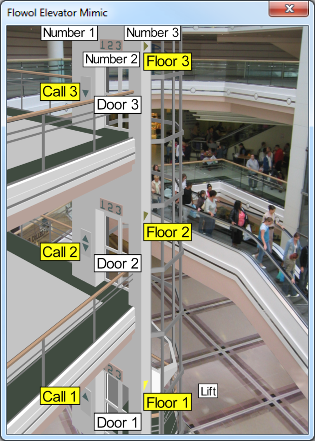
Lifts/Elevators are now a staple of almost all shopping malls.
As the Lift motor moves it trips the Floor 1, Floor 2 and Floor 3 inputs as it reaches each floor.
Each floor has a Door motor, a Call button input and a Number output.
¶ Activity 1: Floor Indicator Lights
Build a flowchart to turn on the Number 2 indicator light when the lift reaches that floor (Floor 2). Turn off the light 3 seconds after the lift has moved away from that floor.
Build two other similar flowcharts to control the other indicator lights.
¶ Activity 2: Elevator Doors
Create 3 subroutines to control the opening and closing of the doors on each floor. In each subroutine you will need to open the doors (motor forward), pause while the door is open and close the doors (motor reverse).
Drag a Start symbol onto the workspace and then call (invoke) each subroutine in turn to test their operation. Once testing is complete, remove this test procedure.
¶ Activity 3: Controlling the Lift/Elevator Movement
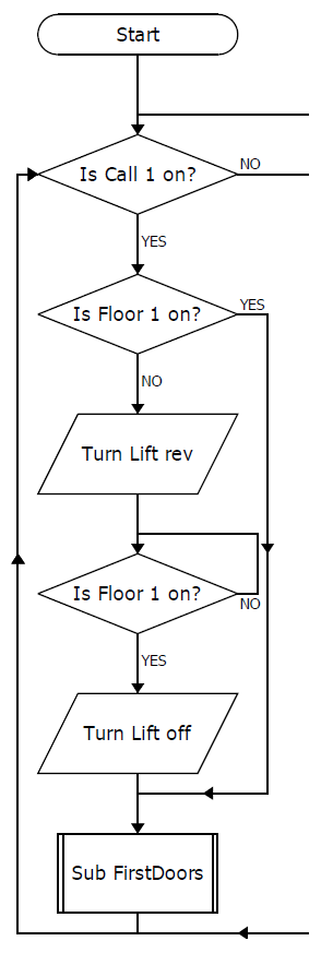
There is a lot to consider when building the flowchart to control the lift/elevator movement.
The partial flowchart to the right is a possible way of moving the lift to the bottom floor (Floor 1) when the Call 1 button is pressed.
Either design your own solution, or copy the flowchart shown and extend it to the right to service the other floors. Servicing the top floor (Floor 3) is very similar to servicing the bottom floor. However when servicing the middle floor (Floor 2), the flowchart will need to see where the lift is located to determine whether to move the Lift up (forwards) or down (reverse).
The subroutine FirstDoors was created in Activity 2.
¶ Activity 4: Using 2 Call Buttons on the Middle Floor (Very Hard)
Create a project using mimic option 4, which adds another control button on the middle floor.
With this option it would be possible to intelligently control the lift movement when multiple floor buttons are called. In this case the lift would only stop at the middle floor if it is moving in the desired direction.
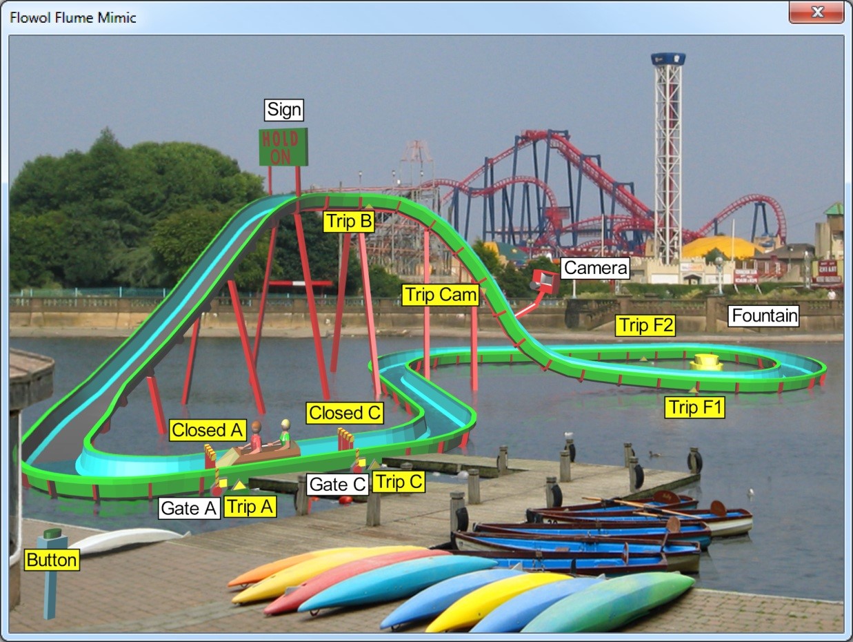
¶ The Theme Park Log Flume
Create a project following the directions above, selecting the Flume mimic. There are two Mimic Options for this mimic, simple and complex. The simple model uses one log and the complex two. Solve the one-log flume first.
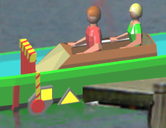
The theme park management decided to develop one end of their boating lake by having a water flume constructed.
¶ One-Log Flume Ride
¶ Activity 1
The mooring deck worked well for the boats, but what changes would you like to introduce now that this landing area is needed for the flume?
¶ Activity 2
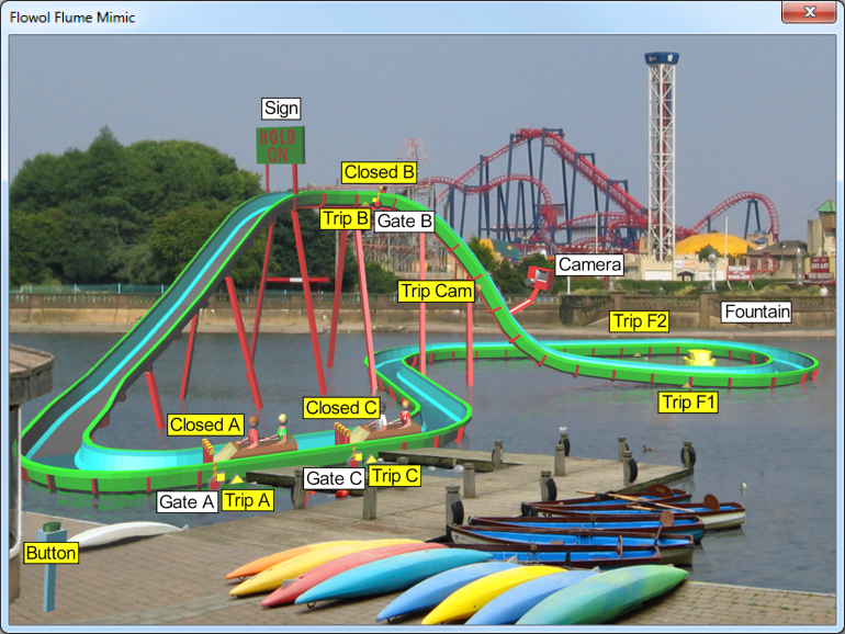
Open the Flume mimic and explore its functions. By default the mimic has one log and two gates (Gate A and Gate C). Click on the Gate motors in the Status Panel to open the gates. In this mimic, the ramp winch and water pump are running continuously so that the log movement can only be controlled by opening and closing the gates.
As the log moves around the ride, you will observe some of the inputs change automatically. These are virtual inputs. The yellow triangles are Trip sensors which are activated when the log is over them. The yellow squares are limit switches on the gates indicating when the gate is closed.
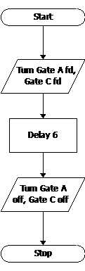 cFirst build this test program to open the gates to allow the log to move. Run the program and observe the following:
- Trip A: The start gate Trip
- F1: Bottom of the chute
- Trip B: Top of the ramp Trip
- F2: Past the fountain
- Trip Cam: Down the chute Trip
- C: The finish Gate.
¶ Activity 3
Build a program to illuminate the message board (Sign output) only while the log is climbing the ramp. Test your solution by running your program alongside the program you built in Activity 2. Perhaps modify your program to make the message flash repeatedly to increase its importance.
¶ Activity 4
Part of the enjoyment of having a day at a theme park is remembering the day and reliving the moment. Now build a program to trigger the Camera as the log plunges down the chute. (Ensure your program doesn’t flash multiple times by checking that the trip input has gone off before the camera can flash again).
¶ Activity 5
Let’s get the riders a little wet. Construct a program to turn on the Fountain motor when the log is passing by. Since the fountain is a motor, change the power of the fountain pump. Perhaps have the fountain working at a low level continuously but increase it when the log passes by.
¶ Activity 6
Controlling the Gates

Remove the simple gate opening program. You now need to use the kiosk Button to operate the ride by controlling the Start and Finish gates.

It is good practice to build subroutines to open and close each gate. First build a subroutine, named OpenA, to open Gate A using a delay while the motor is on (forward). Then build another, named CloseA, (shown left) to close it. This time use the limit switch Closed A to stop the motor.
Using the limit switch has two advantages:
1. The motor stops precisely when the gate is closed.
2. We can be sure that the gate really has closed.
Construct and complete this main flowchart to release the log waiting at the start position when the kiosk Button is pressed. The decision symbols at the top need to check if the Button is pressed AND the log is at the start gate (Trip A). The flowchart then needs to open the gate. Once the log passes the next trip switch on the track, the gate should be closed.
Now build a similar set of procedures to release the log when it is at the finish gate. Again, use the kiosk Button, together with the Trip C to achieve this. Make sure that the finish gate is closed again once the log passes through.
¶ The Theme Park Log Flume with Two Logs
Configure the mimic to use two logs by creating a new Log Flume project and choose the mimic option "complex."
To avoid a collision between the two logs, we now have 3 gates to divide the ride into 3 sections.

¶ Activity 7
Controlling the Two Log Flume
First build the subroutines needed to open Gate B.
Now we will need 3 main routines, one to manage each gate. For the start gate (Gate A) to open, we need the following conditions:
• Button to be pressed AND
• A log at the start position (Trip A On) AND
• No log at the top (Trip B off) AND
• The top gate is closed (Closed B on).
Add these conditions to your Start Gate routine from Activity 6.
Now run your whole program and press the kiosk Button. Good Luck! Each time you run the program, the logs and gates reset to their initial positions.
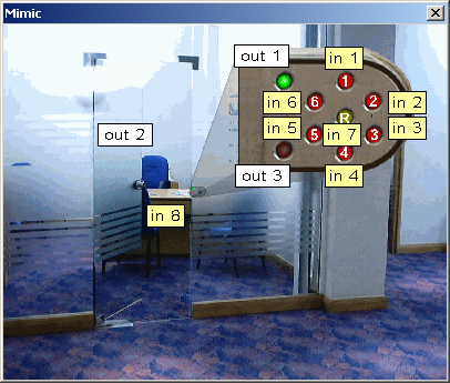
¶ The Burglar Alarm
Create a project following the directions above, selecting the Burglar Alarm mimic.
Keeping our homes safe:
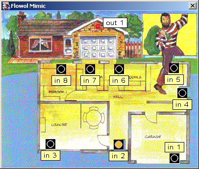
Open the ‘Burglar’ mimic with its labels. Explore what the mimic can do by clicking on the active parts of the mimic or the numbers on the monitor bars.
- Push buttons 1 to 8: Inputs 1-8
- Alarm siren: Output 1
¶ Activity 1
Construct a flowchart program to turn on the alarm siren when any of the inputs are pressed. Make the siren go off again 5 seconds later.
¶ Activity 2
Modify your program by first removing input 2 as the alarm sensor near the front door, and use it as a switch to activate or set the alarm. This input should then need to be pressed again to de-activate the system whether it has been triggered or not.l
¶ Traffic Lights
Create a project following the directions above, selecting the Traffic Lights mimic.
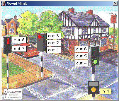
- Push button - - - - - - - -Input 1
- Green Light- - - - - - - Output 1
- Amber Light - - - - - - Output 2
- Red Light - - - - - - - - Output 3
- 2nd set of lights–Outputs 4 - 6
- Walk - - - - - - - - - - -Output 7
- Stand- - - - - - - - - - -Output 8
¶ Activity 1
Create a program to control the first set of traffic lights (Outputs 1 – 3) in the usual, continuous sequence.
¶ Activity 2
Modify your program to control both sets of lights.
¶ Activity 3
Use the walk and stand symbols and just the main set of lights to create a pelican crossing (building subroutines might be useful).
¶ Activity 4 (Advanced)
At a junction the pedestrians usually cross only when both sets of lights are at red. Look at activity 2 again and modify the sequence so that each set of lights become red before the others start changing to green.
When the button is pressed you now need to hold the lights at red until the pedestrians have been given time to cross. When the pedestrians walk time has finished, the light sequence should be allowed to continue (you may need to use a combination of subroutines and variables for this).
¶ The ‘Automatic Washing Machine’
Create a project following the directions above, selecting the Automatic Washing Machine mimic.
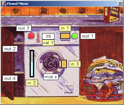
Control should make our lives better in some way. How did people do their washing before the automatic washing machine?
- Start switch - - - - - Input 1
- Water level - - - - - Input 2
- Door switch - - - - - Input 3
- Water temperature - - Val 1
- Indicator light- - - Output 1
- Water IN pump - - Output 2
- Water heater - - - Output 3
- Water OUT pump- Output 4
- Drum spin - - - - -Motor 3 Fd
- Drum wash - - - -Motor 3 Rev
¶ Activity 1
Make a list, in the right order, of the different processes carried out by an automatic washing machine. Think about the safety features e.g. what must not happen until: ?
¶ Activity 2
Construct subroutines for each process and then build a main routine to produce a washing cycle.
¶ Activity 3
In our machine we will assume we need the water temperature to be at least 45 degree C. If you have not already done this, build a flowchart program to heat the water, if it is cooler than 45 deg C.
¶ Activity 4
Make sure you have indicated when the wash cycle has finished. Also ensure that the wash cycle can not restart until the next batch of clothes has been put into the machine.
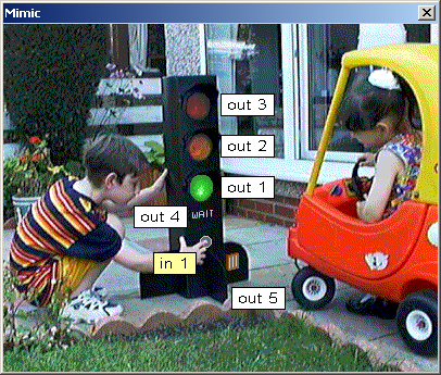
¶ Lights and Pelican Crossing
Create a project following the directions above, selecting the Lights mimic.
Crossing a road safely:
Explore what the mimic can do by clicking on the active parts of the mimic.
- Green light - - - - Output 1
- Amber light - - - - Output 2
- Red light - - - - - - Output 3
- Wait sign - - - - - - Output 4
- Beeper - - - - - - - Output 5
- Push button - - - - Input 1
¶ Activity 1
Starting with the green light ON, create a program (flowchart) to provide the instructions for the three traffic lights to operate continuously in the usual sequence.
¶ Activity 2
Modify the flowchart by introducing the input switch, so the lights stay green unless a pedestrian pushes the button to make the lights stop the traffic.
¶ Activity 3
Introduce the instructions to the program so the WAIT sign reminds the pedestrian only to cross when it safe.
¶ Activity 4
Using the beeper (Output 5), modify the system even further to help those pedestrians who cannot see easily.
¶ Clown Mimic
Create a project following the directions above, selecting the Clown mimic.
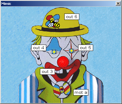
- Nose light - - - - - Output 3
- Eye - - - - - - - - - Output 4
- Other eye - - - - - Output 5
- Buzzer - - - - - - - Output 6
- Bowtie - - - - - - - Motor 1
¶ Activity 1
Draw a flowchart to make the nose flash indefinitely. Refine your instructions until the flashing is pleasing to watch.
¶ Activity 2
Produce another program to make the bee buzz occasionally.
¶ Activity 3
The bowtie is a motor so it can spin both forwards and backwards. Create a routine to control the tie.
¶ Activity 4
The eyes might flash together or alternately. Produce two subroutines for different activities and create a main routine (flowchart) to combine them in an amusing way.
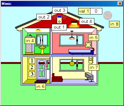
¶ The House
Create a project following the directions above, selecting the House mimic.
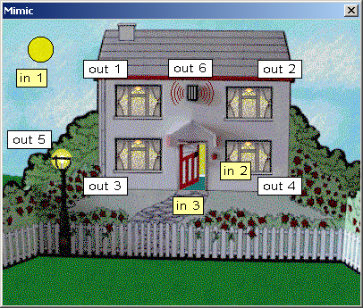
Keeping your house safe and secure
- Light switch - - - - - - - -Input 1
- Bell push - - - - - - - - - -Input 2
- Door switch - - - - - - - -Input 3
- House lights - - - - -Outputs 1-4
- Street light - - - - - - -Output 5
- Alarm buzzer - - - - - -Output 6
¶ Activity 1
Help protect the house by producing a program to turn the street light on automatically only when it is dark.
¶ Activity 2
Having inside lights on during the evening can make the house look occupied. Produce a flowchart to control the inside lights in a suitable way which only happens when it goes dark and will start again the following evening.
¶ Activity 3
On the front door there is a magnetic switch which is off when the door is open. Create the instructions to make the alarm buzzer come on for 3 seconds each time the door is opened. You might try making the buzzing intermittent.
¶ Activity 4
Instead of having a front door bell, use the ‘bell push’ button to trigger the alarm buzzer!
¶ Patrol Crossing
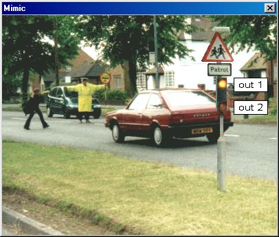
Create a project following the directions above, selecting the Patrol Crossing mimic.
¶ Activity 1
Make the lights (outputs 1 and 2) flash to bring the driver’s attention to the patrol crossing ahead.
¶ Activity 2
Use the patrolman’s ‘lollipop’ (input 1) to activate the lights when the crossing is in use.
Keep us safe with flashing lights.
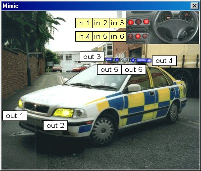
¶ Police Car
Create a project following the directions above, selecting the Police Car mimic.
¶ Activity 1
Use the first switch on the dash- board to turn on the oscillating head lights.
¶ Activity 2
Use the second switch to activate the blue flashing lights with a suitable combination.
¶ Fire Engine
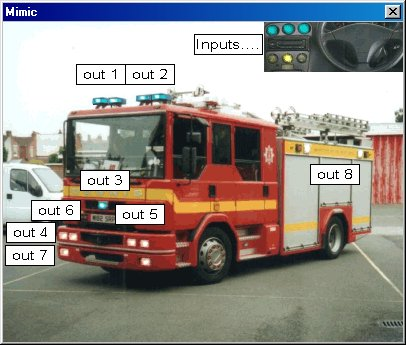
Create a project following the directions above, selecting the Fire Engine.
¶ Activity 1
Use the first switch on the dashboard to turn on the oscillating blue lights (outputs 1 & 2).
¶ Activity 2
Use the second switch to activate a suitable flashing routine for the ‘strobe lights’ (output 3).
¶ Activity 3
Use another switch to turn on the incident lights (output 8) on the side.
¶ Activity 4
The headlights and spotlights can also be operated. Produce some suitable sequence to control them.
¶ Water Chute
Create a project following the directions above, selecting the Water Chute mimic.
A water chute can be fun and safe, providing we think before we go.
The water chute has four input sensors to detect the people at the different positions along the ride. (Click on one person on the mimic to remove the image of the previous one).
There are three outputs: two for the lights at the top of the chute and one for the warning buzzer.
¶ Activity 1
Control the red and green lights at the top of the chute to show when the slide is clear and safe for the next person to go. (note: If inputs 2 or 3 are on, then the slide is still occupied). Note: When the program is running, click on the people (inputs 1,2,3 and 4) on the slide in sequence to simulate their positions and movement on the chute.
¶ Activity 2
Sound the buzzer if a person starts to slide before the last person is safely clear of the splashdown pool.
¶ Activity 3
Use the sensor (input 3) on the edge of the splashdown pool to count the number of times the chute has been used.
¶ Fairground
Create a project following the directions above, selecting the Fairground mimic.
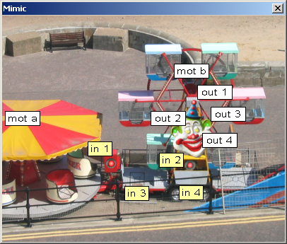
Check the Mimic: Click on the inputs and outputs on the monitor window to see what happens.
Inputs:
- Roundabout start button: Input 1
- Wheel start push button: Input 2
- Pressure pads on footplates: Input 3
- Extra switch: Input 4
Outputs:
- Light on hat: Output 1
- Lights in the eyes: Output 2
- Lights on ears: Output 3
- Nose light: Output 4
- Roundabout: Motor 1
- Ferris wheel: Motor 2
¶ Activity 1
Attract the crowd by flashing the lights on the clown’s face.
Draw a flowchart to turn the lights (outputs 1, 2, 3 and 4) on and off in some interesting way, which then keeps repeating. Change the delays until you get the best routine.
¶ Activity 2
Control the roundabout (carousel).
Probably the safest way to control a ride is to have the operator watching the ride the whole time. Construct a program using the toggle switch input 1, so the operator can turn the roundabout on and off whenever they want.
¶ Activity 3
Now control the Big Wheel.
Now construct another program using the push switch (input 2) to turn the big wheel on, but to turn it off use the pressure pads on the footplates (input 3).
¶ Pirate Ship 2D
Create a project following the directions above, selecting the Pirate Ship mimic.
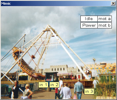
A ride for both young and old.
Check the Inputs and Outputs:
Click on the inputs and outputs on the monitor window to see what the mimic can do.
Inputs:
- Start switch in cabin: Input 1
- Extra switch in cabin: Input 2
- Safety switch on gate: Input 3
Outputs:
- Idle: for small swing: Motor 1
- Power: for high swing: Motor 2
¶ Activity 1
Get the ride swinging.
Construct a flowchart to make the ship make a complete ‘small’ swing (motor 1) which then keeps repeating. Remember to use short delays between the motor commands to make the swing look realistic.
¶ Activity 2
Give the children a ride.
Modify the flowchart in activity 1 so the ship swings only when input 1 is on.
¶ Activity 3
Give the adults a ride.
The real ‘pirates’ should be given a rough ride. Construct another program similar to that in activity 2 to make the ship swing higher (motor 2) only when the switch input 2 is on.
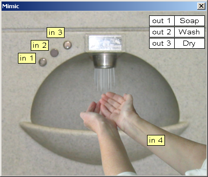
¶ Hand Wash
Create a project following the directions above, selecting the Hand Wash mimic.
¶ Activity 1
Draw a flowchart to squirt soap when input 1 is pressed, another flowchart to spray water when input 2 is pressed and a third flowchart to blow hot air when input 3 is pressed. Run all the flowcharts together and test the program to see if any of the delays need changing.
¶ Activity 2
Modify your program so that at least one of your problems is solved.
¶ Activity 3
Some hand washing machines do not have buttons. Make a new control solution which is fully automatic and starts only when the hands are detected by input 4.
Use the device monitor window to see what the inputs and outputs do.
Inputs:
- Push button for soap: Input 1
- Push button for water: Input 2
- Push button for hot air: Input 3
- Sensor to detect hands: Input 4
Outputs:
- Liquid soap "squirter": Output 1
- Water spray: Output 2
- Warm air dryer: Output 3
¶ Pier Illuminations
Create a project following the directions above, selecting the Pier Illuminations mimic.
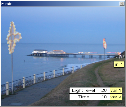
Check the Inputs and Outputs:
Use the device monitor to explore the mimic.
Inputs:
- "Globe" button: Input 1
Outputs:
- Promenade lights: Output 1
- Lifeboat house floodlights: Output 2
- Pavilion & Kiosk lights: Output 3
- Pier strip light: Output 4
- Pier light train: Outputs 5-8
¶ Activity 1
It should be possible to turn the Pavilion floodlights (output 3) on and off when needed. Produce a flowchart which turns on the pavilion floodlights only when the manual switch input 1 is on.
¶ Activity 2
Now build another flowchart which automatically turns on the lifeboat house floodlights (output 2) whenever the light level (val 1) goes below 60 units.
¶ Activity 3
Flashing the promenade illuminations (output 1) makes them more interesting.
Now create another program to operate the promenade illuminations only when the light level (val 1) is below 40 units and the manual switch (input 1) is on.
¶ Activity 4
You could now create programs to control the strip of light (output 4) and the "string" of lights (output 5, 6, 7 & 8) along the pier.
¶ House Alarm
Create a project following the directions above, selecting the House Alarm mimic.
Keep your house secure by having an alarm system and automatic lights.
- Keypad (1,2,3): Inputs 1, 2 & 3 (Can be used to activate and deactivate the alarm and light systems).
- Bathroom window: Input 4
- Bedroom button: Input 5
- Front door mat: Input 6
- Lounge sensor: Input 7
- Sun: Input 8
- Analogue sensor: Val 1
- Warning light: Output 1
- Alarm buzzer: Output 2
- Alarm Light: Output 3
- Floodlight: Output 4
- Hall light*: Output 5
- Lounge light*: Output 6
- Bedroom*: Output 7
- Bathroom*: Output 8
* Not shown on mimic.
¶ Activity 1
Use input 1 to ‘set’ the alarm system and indicate this is done by (output 1 on). The alarm could then be triggered by any of the inputs: 4(off) or 5,6 or 7(on) which then turn outputs 2 and 3 on. (Note: After starting the program, close the window and then set the alarm.) The alarm should then continue, even if these inputs are switched again, until the alarm is deactivated by pressing input 2 on the keypad.
¶ Activity 2
Modify the flowchart so that if input 2 is pressed anytime, the system will deactivate even if the alarm has not been triggered.
¶ Activity 3 (Alarm extension)
An alarm often has more impact if the alarm light flashes. This can be done by having separate flowcharts, for the light (output 3) and the buzzer (output 2) which are similar to the first flowchart. [Alternatively the flowcharts for the light and buzzer can be controlled using a variable in the main procedure].
¶ Activity 4 (Alarm extension)
Modify the deactivating part of the alarm procedure so a code (e.g. 2-1-2) needs to be entered on the keypad before the alarm stops. (This could be a subroutine.)
¶ Activity 5
House security could be improved if an outside floodlight (output 4) comes on automatically when it is dark. This can be triggered by input 8 [the sun] or use analogue sensor val 1.
¶ Activity 6
The inside lights (outputs 5,6,7 & 8) could be made to switch on and off in a sequence when it is dusk. Again use input 8 or the analogue sensor val 1 to trigger this. When away on holiday the sequence would need to start again each evening. (In the solution attached these ‘dusk lights’ are activated by input 3 and de-activated by input 2 only if it is daylight.)
(Inside lights extension): You might have a few different light patterns so that one night is not quite the same as the next.
¶ Water Flume/Chute
Create a project following the directions above, selecting the Water Flume mimic.
The control of the ride would be even safer if the procedure could check if the gates have closed correctly. The ‘flume-X’ mimic uses pressure switches to act as feedback switches (inputs 6,7 & 8) on the gates, which should be clicked on when the gates close. The mimic will turn these switches off again automatically when the gates open. The control of the ride would be even safer if the procedure could check if the gates have closed correctly. The ‘flume-X’ mimic uses pressure switches to act as feedback switches (inputs 6,7 & 8) on the gates, which should be clicked on when the gates close. The mimic will turn these switches off again automatically when the gates open.
Water chutes can be fun and safe, providing we think before we go.
Inputs 1, 2, 3 & 4 are switches which are triggered as a boat/log reaches a position and are used to detect the location of the boats. Clicking on the faded images of the boats will turn that input ‘on’ (shown by strengthen the colour of the image) and turn the previous one off. Clicking on these inputs in sequence (providing the gates indicate you should) makes it possible to simulate the movement of the boats along the ride.
There are three outputs: two for the lights and one for the warning buzzer.
Variable ‘n’ is displayed so the number of times the chute has been used can be counted.
¶ Activity 1
Draw a flowchart to activate the camera (output 8) when a boat is in the correct position. Use either input 3 or val 1. Note: the next flash should only happen when another boat arrives.
¶ Activity 2
Draw a flowchart to allow a boat to move on into the first section between the start and the top. For this to happen there should be a boat at the bottom (input 1 on), no boat at the top (input 2 off) and the top gate closed. The lower gate should then open (mot a forw) and then stop. The winch-belt (output 7) should pull the boat up until it reaches the top (input 2 on). When the boat is at the top, the lower gate should close (mot a rev) and then stop. You could also add a start button (input 5) to allow the boat to start only when the passengers are ready.
¶ Activity 3
Draw another flowchart to allow the boat to move safely from the top control gate to the unloading area at the end of the ride.
¶ Activity 4
Draw yet another flowchart to release the boat safely from the unloading area to loading area of the pond. Note: two boats should be able to operate safely around this ride at the same time.
¶ Extension work
The control of the ride would be even safer if the procedure could check if the gates have closed correctly. The ‘flume-X’ mimic uses pressure switches to act as feedback switches (inputs 6,7 & 8) on the gates, which should be clicked on when the gates close. The mimic will turn these switches off again automatically when the gates open.
¶ Jam Production Line
Create a project following the directions above, selecting the Jam Production Line mimic.
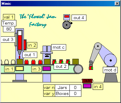
This example has four different processes:
- Jam filler
- Lid/labeller
- Robot arm
- Conveyor belt
Initially these processes could be controlled by subroutines. Later the subroutines should be changed to separate flowcharts for the different processes but linked by variables; i.e. the three manufacturing processes do not start until the conveyor stops, and the three processes must have finished before the conveyor starts again.
¶ The Jam Filler
Draw a flowchart subroutine to ‘squirt’ jam (output 1) for 1 sec. The jam jar must be in place, jam in the filler (inputs 1 & 2 on) and the temp. (val 1) hotter than 70 0C.
¶ The Lid & Labeller
Draw a subroutine to put the lid and label on the jar (mot 3 fd, mot 3 off, mot 3 rev, and mot 3 off) but only if a jar is in position (input3 on). (Use a 0.5 sec. delay between stages).
¶ The Robot Arm
Draw a subroutine controlling the arm. Motor 4 forward to reach the conveyor and reverse to lower the arm to the ground. Input 4 will indicate if the box is in position.
¶ The Conveyor Belt
Use a subroutine to move the conveyor forward (output2) for a specified time.
Construct a Master program to control these four procedures appropriately.
¶ Linking Separate Flowcharts
Delete the master program and change each subroutine to a flowchart with a ‘Start’ at the beginning.
The conveyor output 2 needs to be responsive to the other processes. Use the variables ‘a’, ‘b’ and ‘c’ for the arm, lid/label and filler, and define them as either ‘1’ or ‘0’ to indicate if each process can start or has finished. The conveyor can then be controlled by all the three variables so that it starts when all the variables are ‘0’ and re-sets them to ‘1’ when it stops. (The exact positions of these variables in the flowcharts might affect the efficiency of the system).
¶ Extension
The conveyor movement should also be controlled. It should move and then stop when the jars are in the correct position (use a position sensor (input 1) on the conveyor).
The Jam Heater (Output 3) should turn off when the temperature of the jam is about 70 0C.
Counting the Jars: The variables ‘n’ and ‘y’ can be used to count the jars in each box and the number of boxes filled. In the solution attached, when 6 jars are placed in a box the process stops and the alarm (output 4) sounds until the box is replaced.
¶ Kitchen
Create a project following the directions above, selecting the Kitchen mimic.
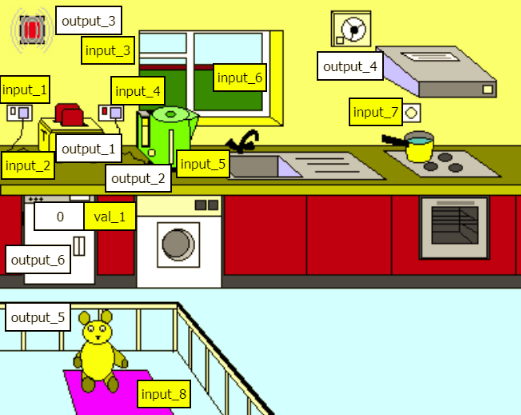
Monitor and control the environment in a kitchen to keep it safe.
- Toaster: output 1
- Kettle: output 2
- Smoke alarm: output 3
- Stove/Cooker hood and fan: output 4
- Teddy bear: output 5
- Freezer alarm: output 6
- Toaster plug switch: input 1
- Toaster slide switch: input 2
- Smoke detector: input 3
- Kettle switch: input 4
- Kettle water level: input 5
- Steam detector: input 6
- Moisture detector: input 7
- Play mat: input 8
- Freezer sensor: value 1
Separate flowcharts can be drawn for each of these activities which then can be run simultaneously.
¶ Activity 1
Turn the toaster (output 1) on for 10 seconds and then turn it off again. The slide switch (input 2) will spring off automatically. The wall switch (input 1) should also be on before the toaster will work.
¶ Activity 2
A large amount of smoke from the toaster may lead to a fire. Turn the smoke alarm (output 3) on if there is too much smoke (input 3). Smoke alarms usually turn off when the smoke clears.
¶ Activity 3
The kettle (output 2) should only turn on if the water level (input 5) is sufficient, and the push switch (input 4) is pressed. When steam is produced, a temperature switch should turn the kettle off (click on steam above the spout for input 6). Note: The kettle should switch off if it boils dry (input 5 off).
¶ Activity 4
The cooker hood and extractor fan (output 4) could be controlled by the moisture detector (input 7). To ensure that the kitchen is clear of moisture, there should be a delay before the fans turn off.
¶ Activity 5
The play pen pressure mat (input 8) and a teddy (output 5) could be used to encourage a child to stay on the mat to play and comfort the teddy. The teddy should start to fuss if the child leaves the mat.
¶ Activity 6
Freezers and refrigerators should stay at a low temperature. If the temperature (val 1) goes above 0 degrees Celsius, then the alarm (output 6) should sound.
Separate flowcharts can be drawn for each of these activities which can then be run simultaneously.
¶ Hydraulic Arm
Create a project following the directions above, selecting the Hydraulic Arm mimic.
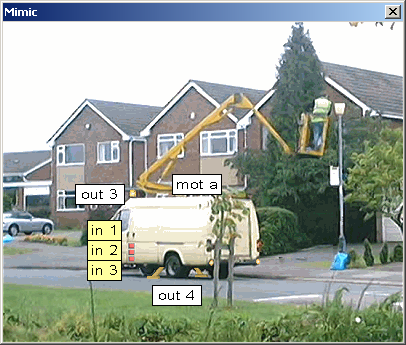
¶ Checking the Inputs and Outputs
Open the ‘arm’ mimic. Click on the inputs and outputs on the monitor window to explore the mimic.
- Top control button Input 1
- Middle control button Input 2
- Bottom control button Input 3
- Raise and lower the arm: Motor 1
- Hazard warning lights Output 3
- Stabilizing feet: Output 4
Let us assume that we are going to use button 1 to control the lights, button 2 the feet and button 3 the hydraulic arm.
¶ Activity 1
Create two subroutines, one to raise the hydraulic arm and another to lower it (motor 1). Create a main routine (with a ‘Start’), which uses button 3 (input 3) to control this up and down movement.
¶ Activity 2
Modify the main routine so that button 2 (input 2) will operate the stabilizing feet (output 4). If your system is safe, the arm should not be able to go up unless the feet are down, and the feet cannot be brought up again until the arm has been lowered.
¶ Activity 3
Now use button 1 (input 1) to control the waning lights (output 3). Again think about the order of the processes (light, feet and arm) to make the system safe.
¶ Activity 4
The system would be even safer if you modify your procedure to make the warning lights flash. (a variable might be needed for this).
¶ Carwash
Create a project following the directions above, selecting the Carwash mimic.
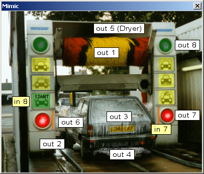
How clean do you want your car to be? A simple wash and rinse or a full shampoo, scrub, blast, wash, rinse and dry!
¶ Checking the inputs
Open the mimic. Click on inputs 1–5 to show how these are displayed on the mimic.
- Wash & rinse button: Input 1
- Wheel scrub button: Input 2
- Foam button: Input 3
- Underbody wash: Input 4
- Dryer button: Input 5
- Emergency crash bar: Input 7
- Start button: Input 8
Outputs:
- Wash brush: Output 1
- Wheel brush: Output 2
- Foam: Output 3
- Underbody spray: Output 4
- Drying fan: Output 5
- Water spray: Output 6
- Red lights: Output 7
- Green lights: Output 8
¶ Activity 1
Create a program to give the car a simple wash using the brush (output 1) and the water spray (output 6). (What should you consider to ensure the body of the car is not damaged?). The system should only begin when the start button (input 8) is pressed.
¶ Activity 2
You may have already used a subroutine but if you haven’t, split up your program now. Make it into a subroutine and a main routine (with a ‘Start’). Now add the control lights (outputs 7 & 8) to your program to indicate to the driver when to move into the carwash, and to show when the wash is complete, and safe for the driver to move out.
¶ Activity 3
Now expand your main program in stages. Write a subroutine to operate a wheel scrub and call this subroutine up from the main routine. Test this addition. Now add similar sub-routines for a foam shampoo, underbody wash, a blow dry etc and call them up in the most suitable order from the main flowchart. (You might want to call up some subroutines more than once).
¶ Activity 4
A customer should be able to select which carwash stages he wishes to have. Introduce the inputs 1 - 5 to the main routine so that some stages occur and others are missed out. Each new customer should be able to have a different selection.
¶ Drinks Machine
Create a project following the directions above, selecting the Drinks Machine mimic.
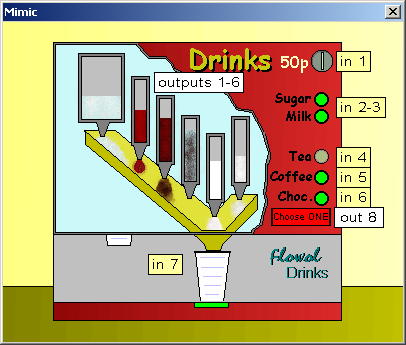
What are the advantages and disadvantages of using a drinks machine?
¶ Checking the inputs and outputs
Open the ‘drinks’ mimic and use the device monitor window.
- Coin (push switch): Input 1
- Sugar button: Input 2
- Milk button: Input 3
- Tea button: Input 4
- Coffee button: Input 5
- Chocolate button: Input 6
- Cup position switch: Input 7
- Hot water: Output 1
- Chocolate dispenser: Output 2
- Coffee dispenser: Output 3
- Tea dispenser: Output 4
- Milk dispenser: Output 5
- Sugar dispenser: Output 6
- Label: Output 8
¶ Activity 1
Write six subroutines, one for each of the processes controlled by outputs 1 to 6. Now create a main routine calling up each of these processes in turn but executing them in the most appropriate order, i.e. coffee before the water etc.
¶ Activity 2
Introduce the inputs 2, 3, 4, 5 & 6 to your main routine so that various processes are only carried out when the appropriate buttons have been selected.
¶ Activity 3
Modify you procedure so that the machine will only work if a cup (input 7) is in place under the spout and the drink has been paid for (input 1). (Note: input 7 can be operated by clicking on either of the two cup positions.) ALSO: you should not be able to get another drink until the full cup has been removed and another one put under the spout.
¶ Activity 4
To stop the machine mixing the drinks, only one of the inputs 4, 5 or 6 should be selected. You could use a variable to warn the customer (output 8) if more than one option has been selected and also stop the machine working if that is the case.
¶ Coupe Car Alarm
Create a project following the directions above, selecting the Coupe Car Alarm mimic.
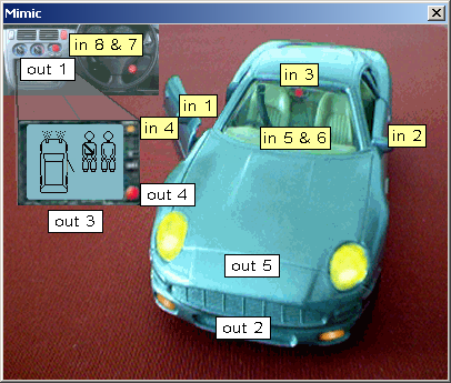
A car and its passengers need to be safe. In this example you will need to provide:
- A system to turn off the headlights automatically when the engine is turned off.
- A system to inform the driver if the seatbelts and doors are not properly secure before moving off.
- An alarm system which can be set and then triggered if the car doors are opened.
Use the device monitor screen to check the inputs and outputs.
- Car door: Input 1
- Car door: Input 2
- Switch to set alarm: Input 3
- Switch to turn on display Input 4
- Seat belt: Input 5
- Seat belt: Input 6
- Engine starter switch: Input 7
- Head light switch: Input 8
- Dashboard alarm light: Output 1
- Orange hazard lights: Output 2
- Display screen: Output 3
- Light on display panel: Output 4
- Car headlights: Output 5
¶ Activity 1
Draw a flowchart to turn on the display screen (output 3), when the switch (input 4) is turned on.
¶ Activity 2
Provide a control system (flowchart) to turn on the headlights (output 5), when the switch (input 8) is turned on. Now include the engine switch (input 7) to ensure that the headlights turn off automatically if the engine if turned off.
¶ Activity 3
The display screen shows if the seatbelts are fastened and the doors closed. Provide a system to turn on the warning light on the display screen (output 4) to bring the drivers attention to the screen if the engine (input 7) is turned on when either of the belts or either door are not secured; (inputs 5 or 6 off) or (inputs 1 or 2 on). Modify your flowchart to make this warning light flash to bring the driver’s attention to it more clearly.
¶ Activity 4
The car alarm can be set by the switch (input 3) on the rear view mirror. To show when the alarm has been set, the light (output 1) on the dashboard should flash. If either of the doors (inputs 1 or 2) are opened, then the orange hazard warning lights (output 2) should flash. This should continue even if the doors are closed again until the mirror switch (input 3) is turned off.
¶ Combination Security Lock
Create a project following the directions above, selecting the Combination Security Lock mimic.
Checking the Inputs and Outputs:
Open the ‘lock’ mimic and explore the mimic with the monitor window.
- Push switches: Inputs 1-6
- Reset push switch: Input 7
- Door handle: Input 8
- Correct combination light: Output 1
- Door opening mechanism: Output 2
- Wrong combination light: Output 3
¶ Activity 1
Construct a flowchart to open the mechanical door (output 2) when the door handle (input 8) is pressed. Leave the door open for 3 seconds and then close it.
¶ Activity 2
Change the flowchart in activity 1 into a subroutine called ‘open’.
Now draw a flowchart for a main routine which calls up this subroutine when four numbers are pressed in the correct sequence. Remember, you should not be able to press the numbers randomly to eventually reach the right combination.
Note: the numbers on the keypad are push switches and will spring off after 0.5 seconds. Put a delay of 1 sec. between each input symbol so the operator will have to press the buttons at roughly 1 second intervals, otherwise the system will reset.
¶ Activity 3
Now add the green light (output 1) to you routines to indicate when the correct combination has been made and the door is ready to be opened.
¶ Activity 4
The red light (output 3) could be used to indicate when the user should start typing in their combination. If the user has taken too long to press the buttons, the light will also show when the system has reset automatically.
¶ Activity 5 (Advanced)
Ideally the user should not have to push the buttons at regular time intervals and the system should be able to be reset anytime by pushing button ‘R’ (input 7) or reset automatically after five wrong numbers have been pressed.
Another approach to the overall solution could be to use variables and to assign a binary number (‘x’= 1, 2, 4, 8, 16, etc) to each input.
¶ Car Park 2D
Create a project following the directions above, selecting the Car Park Barriers mimic.
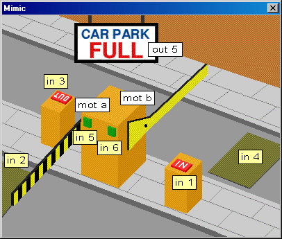
¶ Activity 1
Construct a program to open the ‘IN’ barrier when input 1 is pressed and close it when input 2 is pressed.
¶ Activity 2
Construct a similar program to control the ‘OUT’ barrier.
¶ Activity 3
(Advanced/Optional). Ask you teacher or tutor if you should try this.
Modify your routines to stop the barrier motors when the barriers have reached their highest and lowest positions.
(Note: The ‘Level Crossing’ can also be modified in a similar way. )
¶ Applying Variables
A variable e.g. x or n, can be given a number or can be changed mathematically in a process symbol. The variable can also be used in a decision symbol.
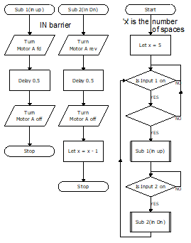
¶ Activity 4
Modify your ‘IN’ and ‘OUT’ routines to stop the IN barrier working if there are no spaces available. The barrier should operate again when spaces become available.
This flowchart shows where I have modified my program to stop cars entering if a space is not available. "x" is the number of spaces in the car park.
¶ Activity 5
Now refine your program or draw a separate flowchart to control the large ‘Full’ sign.